Acoustetron II
The AudioRealityTM Sound Server
Crystal River Engineering, Inc.
Manual Revision 210a, May 1996
Copyright © 1996 Crystal River Engineering, Inc. All rights reserved.
Crystal River Engineering, Inc. acknowledges all trademarks found in this manual.
Crystal River Engineering, Inc. Crystal River Engineering, Inc. 490 California Ave, Suite 200 12350 Wards Ferry Rd. Palo Alto, CA 94306 Groveland, CA 95321 Phone: (415) 323-8155 Phone: (209) 962-6382 FAX: (415) 323-8157 FAX: (209) 962-4873 e-mail: info@cre.com URL: www.cre.com/cre
Contents
Chapter 1 Introduction 3
Overview 3
Organization of this manual 4
Audio spatialization 5
Spatialization inputs & outputs 6
Chapter 2 Getting Started 7
Requirements 7
Hardware 7
Software 7
Input and output amplifiers 7
Output devices 8
Headphones 8
Nearphones 9
Quad speakers 9
Multimedia stereo speakers 9
Other stereo speakers 9
System components and specifications 10
Installation 11
Hardware 11
Startup problems 12
Client software and directory organization 13
Problems 14
Technical support 14
Repair 14
Bugs 14
Chapter 3 Using the Acoustetron II 15
System start up 15
Development usage 15
Run-time usage 17
Test and example programs 18
demo 18
stresstest 18
example 18
bmp1test 18
Application programs 19
audioClient 19
Downloading wave files and other utility programs 20
Environment variables 21
CRE_TRON Software interface 23
Overview 23
Sample rates and driver selection 24
Example code 25
Coordinate system 27
Head tracking 28
Audio sources 29
Sound files 29
External inputs 30
Special topics 31
Atmospheric absorption 31
Spreading loss roll-off 31
Chapter 4 CRE_TRON Function Reference 33
Data structures 33
wavFt 33
Program routines 35
ars_amplfy_surf 35
ars_apply_matl 36
ars_locate_box 37
ars_lock_box 38
cre_amplfy_source 39
cre_close 41
cre_close_wave 42
cre_ctrl_wave 43
cre_define_medium 46
cre_define_output 48
cre_get_sources_playing 49
cre_init 50
cre_locate_head 52
cre_locate_source 53
cre_open_wave 55
cre_send_midi 57
cre_set_dplr 58
cre_update_audio 59
Chapter 5 Glossary 61
FCC Notice 66
Overview
Audio Reality, or real-time 3D audio, greatly enhances the effectiveness of virtual environments. By locating sounds in three-dimensional space, and presenting them to a listener, the Acoustetron II
™ increases an application's ability to transmit information to the user, to stimulate situational awareness, and to create a sense of immersion in a virtual environment. The goal of an AudioReality system is to recreate a sound space in a completely natural and realistic way. When listening to such a system, a user feels immersed by real-world, three-dimensional sounds, rather than feeling aware of listening to a flat, one-dimensional stereo image.The Acoustetron II from Crystal River Engineering, Inc. performs real-time spatialization of multiple real-time audio sources. For each audio input, the system produces Left and Right outputs, which are mixed and played through conventional headphones, nearphones, or speakers. The processing creates the perception that the source is positioned at any specified location in three-dimensional space. In addition, the Acoustetron II provides a wave file editing option, which converts the sound server into a digital sound recording, mixing, and editing environment.
The Acoustetron II is a stand-alone 3D sound server system that can be controlled via a communication protocol (a RS232 serial connection by default) from any client computer that is capable of implementing the communication protocol.
The system consists of four signal processing cards housed in an industry standard 486DX4 PC host controller. Each card holds a Motorola DSP56001 clocked at 40 MHz, and high-resolution stereo A/D and D/A converters, with input and output sampling rates of up to 44,100 samples per second.
The spatialization software included with the Acoustetron II comprises both a software library and several demo programs. The library routines provide automatic detection of the Acoustetron sound server, and translate high-level commands describing source and listener positioning, etc., into the low-level format needed by the system.
Organization of this manual
Chapter 1 "Introduction" describes the audio spatialization process and its implementation on the Acoustetron II.
Chapter 2 "Getting Started" reviews hardware and software requirements for using the Acoustetron II, explains what comes with the Acoustetron II (standard and optional) and how to install it, and tells you how to obtain technical support and service.
Chapter 3 "Using the Acoustetron II" examples how to test your Acoustetron II, and how to write your own programs for controlling the Acoustetron II.
Chapter 4 "CRE_TRON Function Reference" describes the function calls that are used to program your Acoustetron II.
Chapter 5 "Glossary" contains a list a often-used terms relating to AudioReality 3D sound.
Audio spatialization
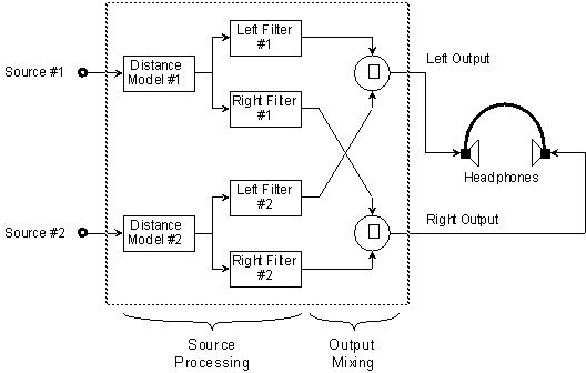
The spatialization processing of two separate sound sources is illustrated in Figure 1. Each of the two sources is pre-processed through a "Distance Model" filter, which simulates atmospheric loss as a function of the specified distance from that source to the listener. The output of this filter is then applied to both Left and Right filters, which together render the source as if it were coming from a certain direction relative to the listener’s head. Finally, the Left and Right outputs from the individual sources are mixed together.
• Figure 1 Spatialization processing on the Acoustetron II (shown for one of its four internal DSP cards).
The Distance Model and the Left and Right filters can be changed dynamically, as often as every 23 msec, or about 44 times per second.
The Left and Right filters are generally known as "Head Related Transfer Functions," or HRTFs. The filter characteristics were obtained from actual measurements on a human head. The Acoustetron II uses Finite Impulse Response (FIR) filters (also known as non-recursive filters).
Spatialization inputs & outputs
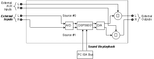
The Acoustetron II offers dynamic selection of two different kinds of sound sources: external mono inputs and 16-bit sampled mono sound files in wave file format.
The only way to enable/disable the External Input is by controlling whatever is connected to the physical input jacks on each DSP card (turning it on or off, or attaching/disconnecting it) - see chapter 3 "External Inputs" for more details. In addition, a monophonic sound file can be digitally mixed (i.e., by the DSP itself) with the external sources.
• Figure 2 Signal flow paths on one of the Acoustetron II's internal DSP cards. The two inputs available to the DSP for spatialization processing are marked in
Chapter 2
Getting StartedRequirements
Hardware
Since the Acoustetron II is a stand-alone system, the only hardware requirements are a serial port a on the client system that you intend to use to control the Acoustetron II audio server. When using the ethernet option the client will require a standard ethernet card.
Software
The Acoustetron II is currently available with client software libraries and serial drivers for MS-DOS, IRIX, SOLARIS, and HPUX operating systems. Controlling the Acoustetron server via ethernet will require the client system to support RPC (Remote Procedure Call) .
The main demo application software for UNIX systems, audioClient, requires an X Windows environment with Motif to operate.
Input and output amplifiers
The input of the Acoustetron II's DSP cards is not pre-amplified for direct microphone input. When digitizing live sound, use a high quality microphone coupled with a microphone pre-amplifier.
The Acoustetron II provides spatialized sound to an external Symetrix headphone amplifier. Please note that the supplied cables that connect the Acoustetron II to the Symetrix amplifier are balanced stereo cables. Do not use unbalanced mono cables to connect the two devices. Headphones, nearphones, speakers, or amplifiers can be connected to the Symetrix outputs. Spatial audio requires a lot of dynamic range to simulate proper distance attenuation. If a sound input or wave file, located at virtual arm's length, does not sound loud with
cre_amplfy_source() set to 0 dB, you need to amplify your source input or wave file gain (see the function description of cre_amplfy_source() in chapter 4 "CRE_TRON Function Reference" for more details).Output devices
Your Acoustetron II can be connected to a number of different output devices. The
cre_define_output() function call is used to select an output device. The default device is headphones. Different devices will provide different levels of spatialization performance. Their ranking in order from best to worst: headphones, nearphones, quad speakers, multimedia stereo speakers, other stereo speakers.Headphones
Headphones are an important part of a virtual acoustic system. Your Acoustetron II system has been optimized for use with supra-aural, "diffuse-field equalized" headphones, i.e. headphones which enclose your entire ear, as opposed to headphones that are placed inside the ear canals. For optimal spatialization results, we strongly recommend usage of high-quality headphones.
The reference headphones for use with Crystal River Engineering HRTF models, are Sennheiser HD540 II's (contact Crystal River for availability).
Depending on your virtual audio application, the difference between acoustically open or acoustically closed headphones might be important. Open headphones (such as the Sennheiser HD540 II's) do not provide a tight seal between the ear and the environment. Such headphones are useful in applications where the user has to be able to hear sounds from the surrounding environment (operator's voice, warning signals) during the simulation. Acoustically closed headphones try to suppress all sounds other than the ones delivered by the headphones. They are useful in completely immersive, virtual environments, or to cancel noisy surroundings (trade shows, noisy work spaces).
If you plan to use electro-magnetic head-tracking devices in conjunction with your Acoustetron II , use headphones with as few metal parts as possible, in order to avoid electro-magnetic interference between headphones and tracking sensors. Try to avoid tracking systems which use transmission frequencies between 20-20,000 Hz (the audible region).
Nearphones
In applications where unobtrusive equipment is important, nearphones can be used instead of headphones. Nearphones are two speakers (left and right signal), placed near (within 25 inches) the user's ear. An example of where nearphones are applicable would be a simulator cab with a projection screen and two speakers mounted next to the user's seat. The user can get in and out of the cab by simply sitting down in a chair. To achieve optimal results the user's head should not move out of the range of the speakers, or turn more than 45 degrees in any direction. The closer the speakers are placed to the user's ears, the better the resulting spatialization.
Quad speakers
If speakers cannot be placed close to the listener, a quad speaker - left front/back, and right front/back - setup is recommended. In this case, the left output of the Acoustetron II would be wired to both left speakers, the right output to both right speakers. The listener should be placed near the center of the square formed by the four speakers.
Multimedia stereo speakers
The term multimedia speakers refers to a stereo speaker setup where the speakers are built in to a monitor or located close to the sides of a monitor. In such a setup the user's position is assumed to be right in front of the monitor, forming a more or less fixed geometry between the listener and the two speakers. Special processing of the left and right audio signals is applied to enhance the 3D effect in such a setup. Please note that multimedia speaker processing is sweet spot (see glossary) limited.
Other stereo speakers
This category includes all other forms of stereo speaker setups. A speaker layout that does not fit the nearphone, quad, or multimedia categories, is unlikely to produce a convincing 3D effect, and is therefore not recommended.
System components and specifications
An Acoustetron II base system consists of the following items:
• 4 DSP signal-processing cards.
• A 486DX4 PC host controller system with 16 Mbytes of wave file playback memory, and 320 Mbytes of wave file storage, DSP cards, Acoustetron II server software, and a headphone amplifier.
• Acoustetron II Client Software Library and Demos and a serial cable for either a PC or UNIX system.
• A 9" monochrome monitor, keyboard, and "Acoustetron II Manual"
• Sennheiser headphones and Symetrix headphone amplifier
• Pre-installed wave file collection (100 wave files of general type: vehicles, explosions, animals, machines, effects, instruments)
• 1/4 inch stereo cables
The system specifications:
• 8 concurrent 3D sources at 44kHz sample rate
• 16 concurrent 3D sources at 22kHz sample rate
• 4 concurrent 3D sources with 6 reflections each at 44kHz sample rate
• full pitch shift control for all sources
• 1 486 100Mhz host CPU
• 4 Motorola 56001 DSPs, running at 40Mhz each
• Maximum system update rate: 44Hz
• Input: 64 x oversampled, 16 bit A/D converters
• Output: 8 x oversampled, interpolating filters
• Stereo crosstalk: 100Hz-100dBV, 1kHz-80dBV, 10kHz-60dBV
Installation
Hardware
Follow these steps to setup and test your Acoustetron II:
1. Connect the Acoustetron II outputs to the Symetrix headphone amplifier using the supplied 1/4 inch stereo cables, connect a pair of headphones to the headphone jack on the headphone amplifier, connect the Acoustetron II to power, connect the monitor and keyboard to the Acoustetron II (both power and monitor cables connect to the back of the Acoustetron II), and power up the system: after system bootup you should see a menu appear that asks you to make a choice.
2. Select "run Menus" followed by "run local demo program" to test the server. You should hear a demo running on your system. If you can see the tumbler spinning on the screen, but there is no audio, check the connection from the Acoustetron II to the headphone amp, and from the headphone amp to the headphones. If there is no tumbler, advance to the next chapter on startup problems.
3. If you hear the demo, your server is functioning properly. Now, reboot the server and let the system select all its defaults. After bootup, you should hear a double beep and see a message on the monitor that shows the Acoustetron II is ready and waiting.
4. Next, connect the Acoustetron II to your client system (PC, SGI, SUN, or HP) via the serial cable that was provided for your specific system. On the server end, the serial cable will fit the COM1 connector, on the client end, the default serial port is port number one (COM1 on PC systems, TTYD1 on UNIX systems). To select a different serial port, please refer to the environment variable section. If you are using the ethernet option, connect the server to your network using one of the three types of connectors found on the network card on the back of the server. Then use the menu to enter the network card connection type and the server's IP address. Ask your system administrator to provide you with this address.
5. Install the Acoustetron II client software onto your client system (from floppy disk switch to floppy drive and type install for instructions, from DAT, or 1/4 inch tape, use tar command to extract software).
6. To test the client/server connection move to the CRE/bin directory on your client system and type demo or test to start up a demo sequence that is controlled from your client system.
7. If your Acoustetron II successfully initializes and plays sounds, your system is installed and ready to use. If the Acoustetron II is not responding correctly please proceed to the next section on startup problems.
Startup problems
Your local demo program does not produce sound and does not start properly (no spinning tumbler on the screen):
either your server environment variables, PC startup files (config.sys and autoexec.bat,) or DSP card address switches have been changed. A call to the factory is your best bet.
Your local demo program does not produce sound but there is a tumbler:
the server is up and running and very likely producing sound. The problem must be in the audio connection between the server and your ears. Check all connectors and make sure the headphone amp is powered on.
The server runs in local demo mode, but does not respond to the client:
The communication link is most likely the problem.
Serial communication link:
Make sure both ends are at the same baudrate (see chapters on Startup menus and Environment variables for details). On UNIX systems, the client software expects a serial port to be set to OFF and 9600 baud. A typical line in the
t1:23:off:/sbin/getty -N ttyd1 co_9600
Ethernet communication link:
Check the physical network connection. Have your system administrator test the IP address that was provided to you. This address should appear at the top right of the server's console. Reenter the physical network connection type using the server's menus. Use the 'ping' program on the client machine to see if the server responds.
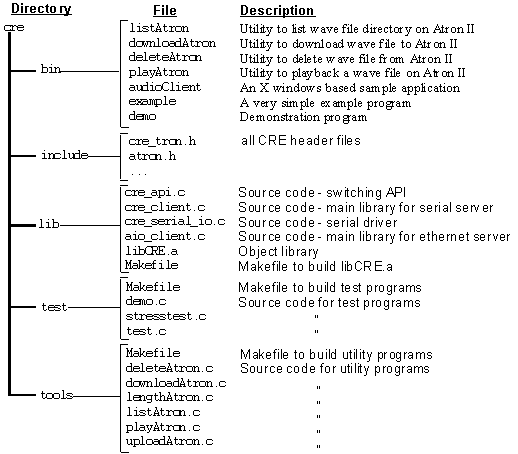
Client software and directory organization
• Figure 3 CRE directory organization, UNIX client.
Problems
Technical support
If you are having difficulties with the operation of your Acoustetron II, be sure to review the Installation procedure described earlier.
If you can’t solve your problem, you should contact technical support at Crystal River Engineering, at the address or phone numbers listed in the inside front page of this manual. Please be sure to have available as much as possible of the following information:
• Acoustetron II software version
• if possible, example code that allows us to reproduce your problem at the factory
Repair
Before returning faulty equipment or media for service, you first need to obtain authorization from Crystal River Engineering or from your distributor.
Bugs
Please report suspected or confirmed software problems to Crystal River Engineering, at the e-mail address or phone numbers listed in the inside front page of this manual. It is essential that you include a complete description of the problem, in sufficient detail that we can reproduce it.
Chapter 3
Using the Acoustetron IISystem start up
On startup, the Acoustetron II system performs a number of self-tests, and then boots up the server. It is useful to talk about two different modes of operation for your Acoustetron II: development or playback . During development of an application, the server should be connected to its monitor and keyboard, in order to make several options and run-time information accessible to the developer. Once an application is developed, and the Acoustetron II is used for run-time playback only, it can be run stand-alone without the need for a monitor or keyboard.
Development usage
On boot-up of the system the following menu is displayed for a short while:
Please make a choice (you have 5 seconds before the default gets selected, press b key to backup to previous menu)
1. run Acoustetron II server in default mode
2. run Menus
3. exit to DOS
If the ethernet option is installed the menu will be slightly different:
Please make a choice (you have 5 seconds before the default gets selected, press b key to backup to previous menu)
1. run Acoustetron II server in ETHERNET mode (default)
2. set Acoustetron II IP address
3. change ethernet connection type (TP, COAX, BNC)
4. run Acoustetron II server in SERIAL mode
5. run Menus
6. exit to DOS
If you don't type anything, choice number 1 gets selected, and the Acoustetron II server starts up waiting for communications from the client, ready to render sounds. Once the server is running, a few keyboard commands can be issued to control it:
SPACEBAR toggles the console display from a static screen to a screen that shows all on-going communication between the client and server (on start-up it is set to static). Please note that printing updates to the screen slows down the framerate of the Acoustetron II.
ESCAPE KEY will restart the server without rebooting the entire system.
'Q' KEY exits the server executable and returns you to the main menu. Once there you can select #3 to get to a DOS prompt.
To change the serial link baudrate for the default startup mode, quit to the DOS file system, change to the C:\CRE\ATRON directory (type 'cd \cre\atron'), and edit the file GO.BAT (type 'edit go.bat'). The lines starting with atronbmp.exe and atronars.exe contain /b384 to select a baud rate of 38400. Change the value to /b96, /b192, or /b1152 for 9600, 19200, or 115200 baud respectively. Save the file and quit the editor.
If you select "exit to DOS" in the main menu, the Acoustetron II will quit and allow you to access its DOS file system. Typing 'start' at the command prompt from any directory will start up the menus again.
If you select "run Menus", the following menu will appear:
Please make a choice (you have 5 seconds before the default gets selected, press b key to backup to previous menu)
1. run Acoustetron II server
2. run local demo program
3. run local test program
4. run wave file development program
(only if option installed)
Selection '2' will start up an AudioReality demo sequence.
Selection '3' will start up the BMP1TEST program (see the chapter on "Test programs" below for description).
Selection '4' will start up the optional wave file editing package (see separate documentation for this option).
Finally, choice '1' allows you to start up the server using via serial communications at a non-default baud rate:
Please select the baudrate at which you want to run the server (you have 5 seconds before the default gets selected, press b key to backup to echo previous menu)
1. run server at 9600 baud
2. run server at 19200 baud
3. run server at 38400 baud
4. run server at 115200 baud
Run-time usage
To use your Acoustetron II with an existing application, simply connect the client and server systems and connect all audio equipment (headphone amp, cables, headphones). The monitor and keyboard are not necessary for operation, since the system can simply be powered up, and is ready to be accessed from the client after a dual beep has been emitted by the Acoustetron II.
Test and example programs
Once hardware and software installation is complete, you may test the Acoustetron II system in a number of ways:
demo
The demo sequence can be started from both the server and the client end. It serves as a verification of server functionality.
stresstest
A test program available on your client system. It will start up eight sounds that are pre-installed on your Acoustetron II system, and will spin them around the listener's head randomly until the program is stopped (CTRL-C).
example
A very simple client example program that moves a sound around in space. This program is a good place to look for a simple code sample to get you started on writing your own Acoustetron II applications.
bmp1test
This program is available on the server only, and can be selected from the startup menu on the Acoustetron II ("local demo test program"). It allows you to test the Acoustetron II locally, independent of a client system that is connected to it.
The program places a listener at the origin of a virtual world, and revolves several audio sources around the user's head. Sounds can be created externally or through wave playback. BMP1TEST includes help screens and displays graphical feedback.
When started, the program will display several status messages as it auto-detects for DSP cards and downloads program code and filter coefficients to the card. Once the program starts up, you should see a continuously updated status message showing the current position of source #0:
#0 (aaaa) < xxxxx, yyyyy, zzzzz> 0.0 dB
where aaaa is the azimuth angle (in degrees) to the source and xxxxx, yyyyy, zzzzz specify its front–back, left–right, and top–bottom coordinates (x,y,z) (in inches), respectively. Initially, the source moves about in a 20-in. horizontal orbit, at ear level (z=0) (refer to Figure 4 for a picture of the coordinate system).
The help screen (displayed when pressing the 'h' key) lists a number of single-keystroke commands which move the orbit up or down, or closer or further away, make it slower or faster, change its direction, or pause its movement. You can also raise or lower the output level for the current source, and you can cycle through all available sources (by typing TAB).
If you supply a "live" source connected to the IN jack at the rear of a card (be sure to make this connection with the power off), the Left channel will be spatialized as source #0, and the Right channel will be source #1.
Another help screen appears when the 'F1' key is pressed. It explains the playback of wave files.
Application programs
The following sample application is provided on UNIX platforms:
audioClient
If running X Windows with the Motif widget set, the audioClient program can be used to verify the functionality of your Acoustetron II. Once started on the client, it presents a graphical user interface, and a two dimensional graphical representation of the listening space, that allow you to load wave files, play them, and move the sounds and the listener around in a space that includes sound reflecting walls.
Downloading wave files and other utility programs
Several utility programs are provided on the client system (see Software and directory organization in Chaper 2).
•
downloadAtron: this utility, if invoked with one or more arguments, downloads wave files (specified by arguments) from the client system to the Acoustetron II server.NOTE: the wave files MUST be 8 or 16-bit, mono, 44,100 or 22,050Hz sample rate. The only recognized format is .WAV, any files ending in other extensions are assumed to be raw data. In addition, Acoustetron II file names can only be EIGHT CHARACTERS LONG, with a 3 character extension.
downloadAtron will truncate any names longer than 8 characters and automatically append a .wav at the end.•
listAtron: prints out a listing of the wave files currently stored and available on the Acoustetron II server. NOTE: when using the ethernet option use the dirAtron utility program instead.•
deleteAtron: this utility expects a filename of a wave file stored on the Acoustetron II, and deletes that file.•
playAtron: this utility expects a filename of a wave file stored on the Acoustetron II and a gain value (default is 0 dB), and plays the file back once.
There are additional utility programs that work with the ethernet option only.
•
uploadAtron: this utility, if invoked with one or more arguments, uploads wave files (specified by arguments) to the client system from the Acoustetron II server.•
dirAtron: similar to the listAtron program, this utility prints out a list of files that are currently stored on the Acoustetron II server. In addition to the filename this utility will also show the size of each file in bytes.•
getserverstats: displays the server's current status which includes the server software version number, number of sources, a counter that is incremented each time one of the sound cards generate an interrupt, and a counter that is incremented each time a bad UDP packet is received.•
getserverlog: displays a log of all commands that the server received from the client.
Environment variables
The Acoustetron II server can be controlled using the following (optional) "environment variables" on the client system:
|
Variable |
Description |
Default (if not set) |
|
TRONCOM |
selects communication parameters |
1@384,30 |
|
TRONDEV |
overrides the serial port device name |
/dev/ttyd1 (UNIX)COM1 (PC) |
The TRONCOM variable needs to be set if you want to operate your Acoustetron II on a different setting than serial port 1, at 38400 baud. The syntax is as follows:
setenv TRONCOM x@yyy,zzz
where x is the serial port number (TTYDx or COMx), yyy the baudrate divided by 100, and zzz the time-out period (the amount of time the client will wait for a response from the server on an init() call).
The TRONDEV variable is optional and only needed if your client system's serial port has a different descriptor than the defaults. For example,
setenv TRONDEV /dev/ttya
sets the serial port device to
TTYA from TTYD1.TRONDEV will override the port number defined by TRONCOM the variable.When using the ethernet option the TRONDEV environment variable is not used and the TRONCOM has no default. It must be set to the IP address of the Acoustetron II server. For example,
setenv TRONCOM 206.119.89.168
or
setenv TRONCOM <hostname>
CRE_TRON Software interface
Overview
CRE_TRON is a 3D audio programming interface that was developed by Crystal River Engineering to facilitate the creation of interactive three dimensional AudioReality sound spaces.
The goal of the CRE_TRON API is to allow a user or developer to build up a sound space using the concepts of physical reality without having to know about the underlying algorithms, implementation or audio hardware.
This API implements the concept of a sound space in the form of easy-to-understand objects. Objects include sound emitting sources, sound reflecting surfaces, and sound receiving listeners. Sounds get created by sources, such as a ringing phone, propagate through space, bouncing off passive objects such as walls, and finally reach a listener's ears, where they are received and interpreted.
The C function calls listed below are used to write programs to control the Acoustetron II. They are described in detail in the "CRE_TRON Function Reference". A good place to start programming is by expanding on the demo.c example code in the CRE/TEST directory.
The function calls that allow a programmer to interact with the Acoustetron II can be grouped into the following categories:
• Utility functions that initialize, update, and close the hardware, declared in CRE_TRON.H:
cre_init (driver, head, sources, mode);
cre_update_audio ();
cre_close (driver, head);
• Function that defines the position of the listener’s head, declared in CRE_TRON.H:
cre_locate_head (id, hloc);
• Functions which allow for the definition, positioning, and amplification of sound sources, declared in CRE_TRON.H:
cre_locate_source (id, sloc);
cre_amplfy_source (id, dB);
• Propagation medium specific functions, declared in CRE_TRON.H:
cre_define_medium (prm, pts, data);
• MIDI-related functions, which allow for interaction with MIDI devices in the form of MIDI streams and commands, declared in CRE_MIDI.H:
cre_send_midi (src, midistr);
• Functions for opening, playing, and closing sampled soundfiles (wave forms), declared in CRE_WAVE.H:
cre_open_wave (wavefile, mode);
cre_ctrl_wave (src, wave, cmd, data);
cre_close_wave (wave);
• ARS (acoustic room simulation) functions, declared in ARS3.H. Please note that these functions are only supported by the ARS3 driver:
ars_amplfy_surf (int surf, float dB);
ars_apply_matl (int matl);
ars_locate_box (float x, float y, float z,
float sizeX, float sizeY, float sizeZ);
ars_lock_box (int mode);
Sample rates and driver selection
The Acoustetron II can run multiple software drivers. Each driver implements the CRE_TRON software interface, but might offer different functionality (see the description of
cre_init() function call for specific driver details). One of the important distinctions between drivers is the sample rate at which they will run the hardware:
• 44,100 Hz: the sample rate of CDs. Advantage: highest possible quality for audio and spatialization. Disadvantage: highest level of computation.
• 22,050 Hz: the sample rate common in multimedia titles and video games. Advantage: the lower bandwidth and storage requirements increase the number of possible concurrent sounds. Disadvantage: both audio and spatialization quality are reduced (most spatialization information is encoded in high frequencies which get cut off when going from 44kHz to 22kHz).
Different drivers get selected at start-up time by one of the parameters of the
cre_init() call.Please note that independent of driver sample rate, both 22kHz and 44kHz wave files can be played back.
Example code
#define SourceID 0
#define HeadID 0
#define Sources 2
#define WaveFile "TEST.WAV"
#define PanLimit 100.0
void main(void)
{
float step = -0.05;
float SrcLoc[6] = { 10.0, PanLimit, 0.0, 0.0, 0.0, 0.0 };
float HeadLoc[6] = { 0.0, 0.0, -10.0, 0.0, 0.0, 0.0 };
wavFt *wave;
/* initialize two Tron sources, with verbose report */
if (cre_init(Atrn_BMP3, HeadID, Sources, 0) < Ok) return;
{
/* amplify source 0 - default is GAIN_dB_OFF (inaudible) */
cre_amplfy_source(SourceID, GAIN_dB_ON);
/* open WAV file and load wave form using all buffers */
if (!(wave = cre_open_wave(WaveFile, 0))) {
printf("\nwave load error.");
return;
}
/* play open wave form as SourceID with repeat loop */
cre_ctrl_wave (SourceID, wave, WaveCTRL_LOOP, NULL);
/* locate listener once (not moving) */
cre_locate_head (HeadID, HeadLoc);
while(!kbhit()) {
SrcLoc[AtrnY] += step; /* move source location */
if ((SrcLoc[AtrnY]<-PanLimit) || (SrcLoc[AtrnY]>PanLimit))
step = -step; /* reverse panning direction */
/* set new location as location of source 0 in space */
cre_locate_source(SourceID, SrcLoc);
cre_update_audio(); /* flush all changes to DSP */
}
/* stop wave form playback and detach from SourceID */
cre_ctrl_wave(SourceID, wave, WaveCTRL_STOP, NULL);
cre_close_wave(wave); /* close waveform */
}
cre_close(Atrn_CLOS, HeadID); /* close Tron */
}
The example program listed above is a "minimal" program which initializes the Acoustetron II, loads and plays a wave file, turns on a single source to be used, positions a listener in space, moves a source between two points in space, and "displays" the sound space by updating the hardware.
The
cre_init() call will locate and initialize sufficient hardware to spatialize two sources, locate the listener’s head at the origin, and locate a sound source 50 inches directly in front of the head (by default). Since no units are specified, locations will be interpreted in inches, the default units. The HeadLoc variable therefore refers to a position 10 inches below the origin. The source is by default a uniform radiator.After successful initialization, the call
cre_amplfy_source() turns source #0 on. Note that all sources are initialized with no amplification. In order to hear anything from a source after initialization, cre_amplfy_source() must be used.The
cre_open_wave() and cre_ctrl_wave() calls are used to load a wave form from disk and play it.The listener is located once to move from the default position to the one specified by
HeadLoc.Then the program moves the location of source #0 using
cre_locate_source(), and uses cre_update_audio() to flush all changes to the hardware, in order to display the new sound space for the listener, until any character is typed, at which point the hardware is closed.
Coordinate system
The environment in which spatialized sounds can be experienced is described by a three-dimensional coordinate system. Within this coordinate system, six-dimensional vectors are used to specify the position and orientation of the listener’s head and of all sound sources. The inputs to the Acoustetron II (external or wave forms) are mapped to the corresponding locations in the coordinate system relative to the listener’s location.
The Acoustetron II software library represents a six-dimensional location vector as an array of six
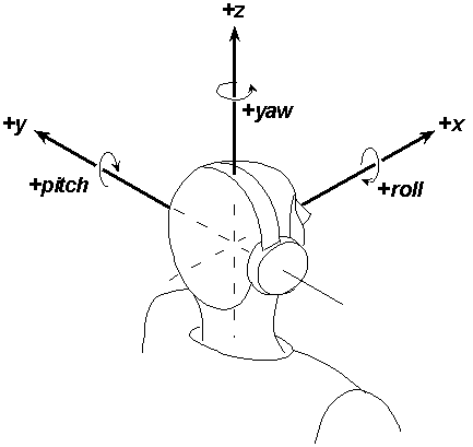
floats (32-bit floating-point number) In this array, the first three elements specify the x, y, and z position in space, in number of "units" (units are selected at initialization of the Acoustetron II—see cre_init()). The second three vector elements specify the yaw, pitch, and roll, in radians. They define the orientation of the source or head at position (x,y,z).The coordinate system is adopted from the vehicle dynamic simulation world. As illustrated in Figure 4, the system is right-handed, with the positive x-axis straight ahead and the positive z-axis ascending vertically. Orientations are specified as right-handed radian Euler rotations, roll, pitch, and yaw, about respective x, y, and z axes. The six-element vector employed in the Acoustetron II software (in using
cre_locate_head() and cre_locate_source()) is ordered < x, y, z, yaw, pitch, roll>. The order of rotations depends upon the rotation basis. With respect to the global coordinate system, from a local coordinate system that initially coincides with the global one, an object is rolled, pitched, yawed, and finally translated.• Figure 4 Six-dimensional coordinate system with listener located at ( 0, 0, 0, 0, 0, 0 ).
Head tracking
Closed-loop tracking of head position can provide an important enhancement to real-time audio spatialization. Software applications using Acoustetron II libraries work well with many six-degree-of-freedom tracking systems, including Fakespace Labs’ BOOM
™ integrated tracker / head-coupled stereo display and popular electromagnetic devices such as Polhemus Navigation’s Isotrak™/Fastrak™ /InsideTRAK™ 3SPACE® tracker and Ascension Technology’s Flock of Birds™ multiple-receiver system. There is no direct software support for tracking devices in the Acoustetron II libraries.Audio sources
Sound files
Each Acoustetron II can playback and spatialize up to eight monophonic sound files at a time when sampling at 44,100Hz, or 16 wavefiles when sampling at 22,050Hz. In order to play multiple sound files simultaneously, each sound file must be assigned to a different spatialization source.
Before a sound file can be played, it has to be loaded onto the Acoustetron II, either by using the downloadAtron utility from the client, or by loading it via the Acoustetron's floppy drive to the c:\cre\waves directory. Once a wave file is loaded, it can then be used in an application using the cre_open_wave() and cre_ctrl_wave() commands.
If you wish to play the same sound file simultaneously on multiple sources, you must open that sound file multiple times as well.
The maximum length of a sound file is limited only by the size of the hard disk, since files get automatically played back from disk when playback memory is exhausted. If you hear stuttering (gaps) in the wave file playback, the system bandwidth has reached its limit, and too many files are being started at the same time.
If a sound file’s name ends with ".WAV", it must be formatted as a "RIFF" file format (per Microsoft Multimedia specifications). WAVE files can be created on the server using the Wave File Editing option available for the Acoustetron II, or using other sound recording and editing tools and downloading the sounds from the client.
External inputs
The Acoustetron II can spatialize up to eight sounds that are connected via live inputs. The external inputs can take their data from microphones, CD players, or other sources of analog audio. The physical connectors can be found on the rear panel of the Acoustetron II. Each of the four DSP cards has an 1/8 inch stereo input connector labeled IN. The left and right lines of these connectors map to spatialization channel id's in the following way:
|
BOARD NUMBER |
INPUT LINE |
SPATIALIZATION CHANNEL ID ARS3 44kHz BMP3 44kHz BMP2 22kHz |
|
0 (top) |
left right |
0 0 0 1 1 |
|
1 (second from top) |
left right |
1 2 6 3 7 |
|
2 (second from bottom) |
left right |
2 4 12 5 13 |
|
3 (bottom) |
left right |
3 6 18 7 19 |
In addition, the AUX connector on each board can be used to mix in stereo signals with the spatialized sound output of the Acoustetron II (however, mixing of spatialized and non-spatialized sounds is not recommended).
The OUT connectors should not be used.
Special topics
Atmospheric absorption
The Acoustetron II includes an "atmospheric absorption" model which attenuates higher frequencies a greater amount than lower frequencies. The degree of attenuation depends on the distance through which the sound travels in the atmosphere—the further it travels, the greater the relative attenuation. As a result, distant sounds have a lowpass-filtered, or "muffled" characteristic.
This model is controlled by a "distance" parameter. For sounds which are close to the listener, as compared with the absorption distance, the relative high-frequency attenuation will be slight. Conversely, sounds whose range is equal to or greater than this distance will incur correspondingly more high-frequency attenuation.
The atmospheric absorption distance can be accessed and adjusted or disabled from its default through the
cre_define_medium() function.Spreading loss roll-off
As sound waves radiate from a point source, their power spreads over an ever-increasing volume of propagation medium. This spreading reduces the sound pressure level as the sound propagates from the source position to the listener position.
The effect of this "spreading loss roll-off" is governed by an exponential curve which scales a sound’s apparent power by the inverse of the sound’s distance raised to an exponent. In a perfect model, this exponent is 1.0, but anechoic simulations may need some adjustment to sound "right."
The exponential factor for all sources may be examined and adjusted from its default value through the
cre_define_medium() function.
Chapter 4
CRE_TRON Function ReferenceData structures
wavFt
The waveform structure and typedef are provided for the application developer to have detailed information on open wave forms, for the purpose of computing useful estimates such length of play. All members are read-only.
typedef struct wavFs {
const char *fname; /* host soundfile filename */
void *pSignal; /* pointer to the signal buffers */
struct wavFs *next; /* linked-list pointer for user */
struct wavFs *synch; /* synchronize with this signal */
int diskBased; /* TRUE if file still open */
double sampleRate; /* in Hz; assumes 44.1kHz */
short numChannels,/* 1 = mono; 2 = stereo */
sampleSize, /* in bytes: 1=8-bit, 2=16-bit */
frameSize, /* in bytes: samplesize*channels */
waveId, /* remote serial identifier */
sourceId; /* value = -1, if not attached */
float pitchFactor;/* pitch shift factor */
unsigned long
numFrames, /* total frames in file */
remFrames, /* # remaining frames NOT loaded */
selFrames, /* length of signal selection */
startFrame; /* beginning of signal selection */
unsigned long
loopStart, /* loop start, in samples */
loopEnd, /* loop end, in samples */
loopCount; /* loop count */
} wavFt;
MEMBERS:
fname - host sound filename string with full path.
pSignal - pointer to waveform signal data (internal use only).
next - pointer to next waveform struct (for application use).
synch - pointer to waveform that this wave will synchronize with.
diskBased - Boolean; non-zero indicates that file is open.
sampleRate - sample rate of the sound signal in samples per second.
numChannels - number of signal channels; 1 = monoaural, 2 = stereo.
Currently, only supports monoaural.
sampleSize - bytes per sample; 1 = 8-bit, 2 = 16-bit. Promotes 8-bit RIFF files to 16-bit playback. Non-RIFF files are assumed 16-bit.
frameSize - bytes per frame; frame = sampleSize * numChannels.
waveId - unique index assigned for remote client/server packets.
sourceId - index of associated source; -1 = unassigned.
pitchFactor - factor by which wave gets pitch shifted
numFrames - total frames in the signal data.
remFrames - unloaded frames remaining on disk.
loopStart - starting point for looping in samples.
loopEnd - ending point for looping in samples.
loopCount - number of times through the loop.
Currently, the following members are not being used:
selFrames - length of selected signal.
startFrame - index of beginning frame in selection.
Program routines
ars_amplfy_surf
|
Synopsis |
#include "cre_tron.h" |
|
Description |
Amplifies or attenuates the dynamic range over distance of the indicated passive surface surf by dB decibels.Note: this call is only supported by the Atrn_ARS3 driver. |
|
Parameters |
surf the index (from zero) of the surface to be amplified. Selected from enum list in CRE_ARS3.H:enum { SURF_FRONT, SURF_RIGHT, SURF_BACK, SURF_LEFT, SURF_CEILING, SURF_FLOOR }; dB the amplification in decibels. The macro GAIN_dB_OFF is provided to definitively shut off a surface. GAIN_dB_ON is 0 dB. Any value less than -120 dB is interpreted as off. |
|
Return Value |
On success |
|
Example |
ars_amplfy_surf (SURF_FRONT, GAIN_dB_ON); |
ars_apply_matl
|
Synopsis |
#include "cre_tron.h" |
|
Description |
Applies an acoustic material with reflection and transmission properties to all surfaces. Materials are selected from a palette of empirically measured material filters. Note: this call is only supported by the Atrn_ARS3 driver. |
|
Parameters |
matl the material to be applied. Selected from enum list in CRE_ARS3.H:enum { MATL_ANECHOIC, MATL_MIRROR, MATL_TEXTILE, MATL_PLYWOOD, MATL_GLASS, LAST_MATERIAL }; Note: anechoic walls are perfect absorbers, they do not reflect any sound. However, the box geometry is still active (sounds can move outside the box). |
|
Return Value |
On success |
|
Example |
ars_apply_matl (TEXTILE); |
ars_locate_box
|
Synopsis |
#include "cre_tron.h" float sizeX, float sizeY, float sizeZ); |
|
Description |
Locates all the surfaces (walls) of a room to simulate the effects of first order sound reflections off of the walls. Sounds that are located outside the boundaries of the box are muffled by transmission loss filters. Note 1: all walls are orthogonal (the room is a box). Note 2: this call is only supported by the Atrn_ARS3 driver. |
|
Parameters |
x, y, z sizeX, sizeY, sizeZ length, width, and height of the room. |
|
Return Value |
On success |
|
Example |
float x, y, z, sizeX, sizeY, sizeZ; x = y = z = 0.0; sizeX = 200.0; sizeY = 180.0; sizeZ = 120.0; ars_locate_box (x , y , z, sizeX, sizeY, sizeZ); |
ars_lock_box
|
Synopsis |
#include "cre_tron.h" |
|
Description |
Locks the box to the listener's position. The listener is always located at the center of the room. The listener's orientation does not affect the box's orientation. Note: this call is only supported by the Atrn_ARS3 driver. |
|
Parameters |
mode |
|
Return Value |
On success |
|
Example |
ars_lock_box (LOCK_ON); |
cre_amplfy_source
|
Synopsis |
#include "cre_tron.h" |
|
Description |
Amplifies or attenuates the dynamic range over distance of the indicated sound source id by dB decibels. The default source gain (GAIN_dB_ON = 0 dB) is set so that maximum possible volume is reached at a distance of 2.5 units from an ear. Distant sound sources may need to be set much higher (as much as +30 dB), in order to be audible at the listener’s position. |
|
Parameters |
id the index (from zero) of the sound source to be amplified. The macro ALL_SOURCES is supported.dB the amplification in decibels. The macro GAIN_dB_OFF is provided to definitively shut off a sound source. Any value less than -120 dB is interpreted as off. |
|
Return Value |
On success On failure Error0 - audio source id is out of range, or no Tron sources have been initialized.Error1 - dB is unreasonable. To prevent floating point overflows dB should not exceed 20 * EXPONENT_LIMIT, defined in ATRON.H. |
|
Example |
cre_amplfy_source (ALL_SOURCES, GAIN_dB_OFF);
|
|
Remarks |
This is the most misunderstood function in the CRE_TRON API. Attenuation over distance is a very important 3D cue, over which the system must have dynamic range to apply. As a sound source gets closer to a receiver, its sound pressure level must increase exponentially (nominally 6 dB for every half of the distance), but there is a maximum volume that audio hardware can (and, for safety reasons, should) reach. We have set the library so that the maximum volume is reached for a 0 dB at 2.5 inches from the receiver. If a source is within this range, our software can provide very little distance cue. If the source is mostly far-field (never comes near the receiver), you can optimize the dynamic range by setting the gain to a higher value. A table relating source amplitude setting to clipping distance may be found in ATRON.H. If you need to adjust the relative amplitude of the source, that should be done at the synthesis of the sound. cre_amplfy_source() will provide such relative amplitude service, but you run the risk of ruining the 3D effect for near field sounds. |
cre_close
|
Synopsis |
#include "cre_tron.h" |
|
Description |
Deallocates host and DSP resources for a given driver and listener (which may then be reallocated with another cre_init() call). cre_close() will gently shut off all audio. cre_close() does NOT automatically close all open wave forms. cre_close() is required to safely terminate a host application. |
|
Parameters |
driver selected from enumeration list in ATRON.H (see cre_init()). The enum Atrn_CLOS shuts down all CRE drivers.head the identifier of an initialized listener to be closed. The macro ALL_HEADS will force all listeners associated with the given driver to be closed. |
|
Return Value |
On success On failure Error0 - no Tron sources have been initialized.Error1 - invalid driver type. Error2 - uninitialized listener identifier head. |
|
Example |
cre_close (Atrn_CLOS,0); |
cre_close_wave
|
Synopsis |
#include "cre_tron.h" |
|
Description |
Closes the waveform wave by unpatching any DSP using it, closing its host file, if open, and freeing the signal and the wave structure. If wave is attached to a sound source and is playing, it will be stopped before the wave is closed. In order to properly deallocate resources, each (successful) call to cre_open_wave() must be balanced with a call to this routine. |
|
Parameters |
wave a pointer to the waveform structure to be closed. |
|
Return Value |
On success On failure Error1 - invalid wave structure. |
|
Example |
wavFt *wavep = cre_open_wave("TEST.WAV",4); ... /* listen to the music */ cre_close_wave(wavep); |
cre_ctrl_wave
|
Synopsis |
#include "cre_tron.h" (int src, wavFt *wave, int cmd, void *data); |
|
Description |
Requests the host to control the waveform wave according to the command cmd, which may be related to source src and may require the host to communicate with the DSP associated with source src . The function is a generic dispatcher that may be extended in future releases. See command descriptions below for specific behavior. |
|
Parameters |
src the index (from zero) of the audio source in reference. The macro ALL_SOURCES is not supported.wave a pointer to the waveform structure affected by all commands except WaveCTRL_STOP.cmd one of the pre-defined command values from the wave_ctrl enumeration:enum wave_ctrl { WaveCTRL_RWND, WaveCTRL_STAT, WaveCTRL_STRT, WaveCTRL_PLAY, WaveCTRL_LOOP, WaveCTRL_PTCH, WaveCTRL_STOP, WaveCTRL_LPST, WaveCTRL_FSTAT }; data NULL, except for WaveCTRL_PTCH and WaveCTRL_LPST |
|
CMD Types |
WaveCTRL_RWND rewinds the current frame position of waveform wave to its first frame. Rewind is useful if the waveform was stopped before finishing its full selection. WaveCTRL_STAT (see also cre_get_sources_playing())tests current waveform wave status with respect to given source src. Alternatively, this command can check wave for any source with src = -1, or check src for any waveform with wave = NULL. cre_ctrl_wave() generates a 4-bit return value, with each bit representing a state of either wave or src:bit 0 - waveform wave playing on source src's DSP. bit 1 - waveform wave playing on some DSP. bit 2 - source src's DSP playing some waveform. bit 3 - source src playing some waveform. A return of zero means that neither wave nor src are busy.WaveCTRL_STRT resets and plays waveform wave from its beginning, patching it through to source src.WaveCTRL_PLAY plays waveform wave from its current frame position, patching it through to source src.WaveCTRL_LOOP plays waveform wave from its current frame position with loop flag enabled. When playback reaches the end of the sound file, the signal is automatically rewound to its beginning. Looping continues, until the playback is stopped (WaveCTRL_STOP), or the loop flag becomes disabled (WaveCTRL_NOLP). See WaveCTRL_LPST for information on setting loop points.WaveCTRL_PTCH sets the pitch shift factor pointed to by data (float *) for wavefile wave (BMP2 and BMP3 drivers only). A value of 1.0 (default) results in no pitch shifting, a value of 2.0 (maximum) will double the pitch of the wavefile, a value of 0.5 (minimum) will half the pitch of the wavefile.WaveCTRL_STOP stops playing any waveform attached to source src, maintaining that wave form's current frame position. |
|
WaveCTRL_LPST sets loop start, loop end, and loop count parameters. src is ignored, data is a pointer to an array of three longs:data[0] = loop start (unsigned long, in samples) data[1] = loop end (unsigned long, in samples) data[2] = loop count (signed long, -1 = infinte looping) WaveCTRL_FSTAT used to return wave file statistics. src anddata are ignored. The following fields in wave will be updated after function exits: |
sampleRate numFrames loopStart
diskBased fname loopEnd
sampleSize loopCount
|
Return Value |
On success On failure Error0 - audio source src is out of range, or no Tron sources have been initialized.Error1 - waveform structure pointed to by wave is invalid. Error2 - command cmd is unsupported. Error3 - DSP conflict, such as wave already playing on other DSP. Error4 - DSP error, such as failed attempt to perform command. Error5 - no interrupt enabled for given DSP. |
|
Example |
wavFt *wavep = cre_open_wave("TEST.WAV", 4); cre_ctrl_wave(0, wavep, WaveCTRL_LOOP, NULL); ... /* do other things while sound plays */ cre_update_audio(); /* tend to playback buffers */ ... /* do other things while sound plays */ cre_ctrl_wave(0, wavep, WaveCTRL_STOP, NULL); cre_close_wave(wavep); |
cre_define_medium
|
Synopsis |
#include "cre_tron.h" |
|
Description |
To allow the user to specify parameters defining the propagation medium model (absorption filter distance and spreading roll-off exponent). The function is a generic dispatcher that may be extended in future releases. See parameter descriptions below for specific behavior. |
|
Parameters |
prm enum ATRNmedDef { AtrnROLLOFF, AtrnABSORBdist }; pts the number of points to be read from the data pointer.data a pointer to at least pts data points. An undetectable error will occur if pts is larger than the number of points available to read. The pointer can be NULL, in which case the first pts points of the existing pattern table will be used. |
PRM Types
|
AtrnROLLOFF The roll-off exponent due to spreading power loss. The spreading roll-off exponent parameter sets the rate at which sound amplitude is attenuated over distance to yield cues in the third dimension. Currently, this parameter can only be set globally, for all sources. The pts argument must be set to one to have the float value pointed to by data set the spreading roll-off exponent, or may be zero or negative to reset the default value, defined by the macro SPREADING_ROLLOFF in ATRON.H. An exponent value given that is out of range will return an error. The exponent must be non-zero positive and less than the value defined by the macro EXPONENT_LIMIT in ATRON.H. |
Remarks:
In a free sound field spreading loss is -6 dB per doubling of the distance (gain proportional to 1.0 / R). However there are few free sound fields in the real world, so the apparent spreading loss depends on the propagation medium's acoustic impedance and elements in the sound field. Since the Tron is only simulating a virtual anechoic environment, a nominal roll-off exponent of 1.0 sounds steep. Typically, roll-off exponents in the range of 0.5 - 1.2 are of interest.|
Return Value |
On success On failure Error0 - no Tron sources have been initialized.Error1 - invalid parameter prm. Error2 - pts is non-zero, but data is NULL. |
|
Example |
/* distance in current units */ float absorb_dist = 100.0; cre_define_medium (AtrnABSORBdist, 1, &absorb_dist); |
cre_define_output
|
Synopsis |
#include "cre_tron.h" |
|
Description |
To allow the user to select the appropriate audio output rendering device. See the list under parameters below for supported devices. See section on "Output devices" in chapter 2 for a discussion of different devices. |
|
Parameters |
device HEADPHONES - default. Use for headphone, nearphone, quad speaker, and generic stereo listening devices.SPEAKERS_NARROW - use this setting for multimedia speakers that are built into a monitor or monitor stand.SPEAKERS_WIDE - use this setting for stand alone multimedia speakers that are located next to your monitor. |
|
Return Value |
On success On failure Error0 - no Tron sources have been initialized. |
|
Example |
cre_define_output (HEADPHONES); |
cre_define_source
|
Synopsis |
#include "cre_tron.h" (int id, int prm, int pts, const void *data); |
|
Description |
To allow the user to specify parameters defining the source rendering model (directional radiation pattern, externalization ON/OFF, and listener linkage). The function is a generic dispatcher that may be extended in future releases. See parameter descriptions below for specific behavior. |
|
Parameters |
id prm one of the pre-defined parameter values from the ATRNsrcDef enumeration:enum ATRNsrcDef { AtrnRADprofile, AtrnSPATIALoff, AtrnHEADlink }; pts the number of points to be read from the data pointer.data a pointer to at least pts data points. An undetectable error will occur if pts is larger than the number of points available to read. The pointer can be NULL, in which case the first pts points of the existing pattern table will be used. |
|
PRM Types |
AtrnRADprofile Defines an audio source's radiation pattern about its boresight axis. The radiation profile of a sound source id is specified with an array of relative sound pressure levels in decibels, pointed to by data, sampled equi- angularly at pts points from the boresight N-pole to S-pole, inclusive. The boresight direction is defined as a source's positive roll axis (the sound source axis parallel to the world coordinate X-axis when source YAW and PITCH are zero). All definable radiation patterns are symmetric about the ROLL axis (i.e., no rectangular horn speakers). For off-axis angles from source to listener that fall between sample points, the profile is linearly interpolated. Designed for empirically sampled data, AtrnRADprofile also provides effective profile definition with very few artificial points. The macro MAX_RADPROFILE specifies the maximum data array size supported. See Figure 5 for example uses of AtrnRADprofile.Note: Uniformly radiating sources save considerable computation and are specially defined by pts = zero. In the special case of pts = 1, the boresight direction is set to the value pointed to by data , while the opposite pole is defined by (*data + GAIN_dB_OFF)/2. If a NULL data pointer is given, the profile is set to the first pts points of the existing table. With this feature you can pre-load the profile array, and then toggle directional radiation on and off with pts .AtrnSPATIALoff By setting this parameter, spatialization for this source is disabled. The monaural sound is patched straight through and mixed with the left and right outputs according to the decibel values to which data points, enabling simple panning. If pts = zero, the previous panning mixture values are used. If pts = one, the given value is applied to a balanced mixture. If pts is greater than two, an error is returned. If pts is negative, spatialization is re-enabled, which is the default. The source is convoluted through a flat filter, so the latency remains the same as if spatialized.AtrnHEADlink By setting this parameter, the source maintains its relative position and orientation to the listener's head for all head positions and attitudes given. When AtrnHEADlink is enabled, all calls to cre_locate_source() establish a new fixed relative position as a difference of the global coordinates of head and source locations given. This parameter takes no data arguments and the data term is always ignored. The pts argument is interpreted as the head index. A negative value for pts unlinks the sound to all listener head positions. |
|
Return Value |
On success On failure Error0 - audio source id is out of range, or no Tron sources have been initialized.Error1 - invalid parameter prm. Error2 - pts out of range. Error3 - parameter specific error, see parameter descriptions. |
|
Example |
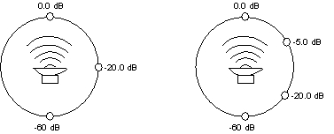
const float rad_table[4] = { 0.0, -5.0, -20.0, -60.0 }; cre_define_source (mysource, AtrnRADprofile, 4, rad_table); |
|
Remarks |
A positive value for pts requires that the source orientation be maintained as well as translation. Hence, all subsequent calls to cre_locate_source(), regarding the same source id, must specify yaw and pitch. Roll orientation is still ignored, because the radiation pattern is symmetrical about the roll axis. |
• Figure 5
cre_define_source() examples for two different radiation tablesrad_table[3] = rad_table[4] =
{0.0,-20.0,-60.0} {0.0,-5.0,-20.0,-60.0}
cre_get_sources_playing
|
Synopsis |
#include "cre_tron.h" |
|
Description |
This call returns status information on all sources, as to whether they are currently playing or stopped. Note: this function call is more efficient than calling cre_ctrl_wave() with the WaveCTRL_STAT command. |
|
Parameters |
sources |
|
Return Value |
On success On failure Error0 - audio source id is out of range, or no Tron sources have been initialized. |
|
Example |
int sources[8]; cre_get_sources_playing (sources); |
cre_init
Synopsis
|
Description |
Computes, detects, and allocates resources (i.e., Trons and host memory) to provide the services specified by driver to listener head for the requested number of sources. The DSP driver is loaded from the host to the resourced hardware and booted. All host and DSP memory is initialized with reasonable values. The listener's head is located at the origin. All sound sources are initially positioned at the full RESPONSE_DISTANCE (radius of actual HRTF responses given in ATRON.H) in front of the listener's head.Important: All gains are initially set by cre_init() to GAIN_dB_OFF. This is so that, if an analog input is currently active at full level, it will not "pop" on without user control. The programmer MUST make use of the cre_amplfy_source() function to enable the user to hear Tron output after initialization. |
|
Parameters |
driver |
enum ATRNdrv {
Atrn_ARS3, - A
RS3.LOD 4-src 44khz room simulationAtrn_BMP2, -
BMP2.LOD 16-src 22khz, DopplerAtrn_BMP3, -
BMP3.LOD 8-src 44khz, Doppler};
head listener identifier to be initialized. An identifier must beunique for each listener and can be any integer from 0 to 63. If the listener identifier has been previously initialized, the requested sources are additional. |
sources total number of sources heard by the listener’s head.mode bit field "ORed" from ATRON.H macros and enums: |
units—select one from enum list:
enum ATRNunits {
AtrnINCHES, Atrn_FEET_, AtrnMMETER, AtrnCMETER, Atrn_METER
};
|
Return Value |
On success returns the number of sources allocated. On failure Error1 - memory allocation error or DSP binary load failure, see cre_error() for detailed failure. Error2 - incompatible or invalid DSP binary loaded. Error3 - acoustic headmap invalid or load failure. Error4 - invalid driver type. Error5 - invalid listener identifier. Error6 - server response error. |
|
Example |
if (cre_init(Atrn_CMP1,0,2,(AtrnCMETER | _VERBOSE_)) < Ok) |
|
Remarks |
An Acoustetron may be initialized only once, for a given listener. After a successful initialization, all subsequent calls to cre_init() are ignored until a cre_close() has been performed. Since all listeners share the same sound space, the same number of sources must be requested for each head. |
cre_locate_head
|
Synopsis |
#include "cre_tron.h" |
|
Description |
Locates the head of a listener six dimensionally in world coordinates. It only updates changes from previous state, recalculating pinnae locations as needed. This function does not affect DSP processing until a synchronization call to cre_update_audio() is successful. |
|
Parameters |
id the identifier of a listener to be defined.headLoc a pointer to an ordered array of six floats as follows: |
AtrnX
world x-axis coordinate.AtrnY
world y-axis coordinate.AtrnZ
world z-axis coordinate.AtrnYAW
angle of -π to π from the world x-axis about the world z-axis of the projection of the head’s x-axis onto the world x-y plane. Looking down at the x-y plane a counter-clockwise rotation is positive.AtrnPTC
angle of -π/2 to π/2 from the world x-y plane of the head’s x-axis about the world y-axis. Remember that with x forward and z up, a positive pitch is down.AtrnROL
angle of -π to π from the world y-axis about the world x-axis of the head’s y-axis. From the listener’s point of view, a clockwise roll of the head, rolls y into z and is therefore positive.|
Return Value |
On success On failure Error0 - no Trons have been initialized.Error1 - headLoc is NULL. Error2 - uninitialized listener identifier id. |
|
Example |
const float headLoc[6] = {10.0, 20.0, 30.0, 0.0, 0.0, 0.0}; |
cre_locate_source
|
Synopsis |
#include "cre_tron.h" |
|
Description |
Locates an audio source id six dimensionally in world coordinates. This function does not affect DSP processing until a synchronization call to cre_update_audio() is successful. |
|
Parameters |
id sourceLoc a pointer to six floats in order as follows: |
AtrnX
world x-axis coordinate.AtrnY
world y-axis coordinate.AtrnZ
world z-axis coordinate.AtrnYAW
angle of -π to π from the world x-axis about the world z-axis of the projection of the source’s x-axis onto the world x-y plane. Looking down at the x-y plane, a counter-clockwise rotation is positive.AtrnPTC
angle of -π/2 to π/2 from the world x-y plane of the source’s x-axis about the world y-axis. Remember that with x forward and z up, a positive pitch is down.AtrnROL
angle of -π to π from the world y-axis about the world x-axis of the source’s y-axis. From the source’s point of view, a clockwise roll of the sound rolls y into z and is therefore positive.|
Return Value |
On success On failure Error0 - audio source id is out of range, or no Tron sources have been initialized.Error1 - if sourceLoc is NULL. |
|
Example |
const float srcloc[6] = {-10.0, -20.0, 0.0, 0.0, 0.0, 0.0}; |
|
Remarks |
Only the first three floats are used when the audio source is in uniform radiation mode. However, as a safe programming practice, you should always maintain pointers to six-element data structures. AtrnROL is not presently used since non-uniform radiation is symmetric about the boresight roll axis, but it should be maintained for future compatibility. |
cre_open_wave
|
Synopsis |
#include "cre_tron.h" |
|
Description |
Opens a sound file referred to by the filename wavefile from the Acoustetron II's disk, returning a pointer to the allocated wavefile structure wavFt. Sound file control, such as playback through a particular source, is effected through cre_ctrl_wave(). Currently, the only formally recognized sound file format is RIFF (MS Windows .WAV format). Note that independent of which driver (22kHz, or 44kHz) is being used, both 22kHz and 44kHz wave files can be opened and played back.Note: Since cre_open_wave() dynamically allocates host memory and may keep host disk files open, every cre_open_wave() should be paired with a cre_close_wave(). Waveform open-close pairs are independent of cre_init() - cre_close() pairs. The maximum number of concurrently open wave files is 127 (see remarks below). |
|
Parameters |
wavefile a string which specifies the filename to be loaded from disk. If the filename ends with ".WAV", the file must have a valid RIFF format header.mode the amount of memory that is being allocated for the file in 32kbytes * mode. See remarks below for a discussion on what mode values to use. |
|
Return Value |
On success On failure NULL - filename wavefile not found, could not be opened, was invalid, or system out of memory. |
|
Example |
char *fname = "test.wav"; |
|
Remarks |
There are two fundamental ways to load a wave file: mode 0 which loads the entire wave file into memory, or mode > 0 which loads mode*32kbytes of the wave file into memory. During wave file playback, a mode 0 file will be played straight from memory, whereas a mode > 0 file will be played back from hard disk using the mode*32kbytes as playback buffers. Adjusting the mode parameter to different values affects three areas of performance: 1. delay caused by open_wave command: the open command returns a structure after opening and loading up the wave file. Since loading the data off the hard disk takes some time, the higher the mode value, the longer cre_open_wave() will take before it returns. The fastest possible open is about 30-40 milliseconds for mode values of 1, 2, 3, and 4. After that each additional 32kbytes takes another 5-10msecs to load, e.g. mode 8 would equal about 40msecs+4*7.5msecs=70msecs. Finally, mode 0 takes longest because it loads the entire file, with the delay being approximately 100msecs + 25msecs for each 100kbytes of wave file length. For example, a 300kbyte long wave file will take about 100msecs+3*25msecs=175msecs to open. A 3mbyte long file will take about 100msecs+30*25msecs=850msecs. 2. number of open wave files: a base Acoustetron II system with 16mbytes of memory, has 8.3mbytes available for opening wave files. If specifying mode 2, the maximum number of wave files (127) can be fit into memory (127*64kbytes= 8.3mbyte). For mode 0, the size of all concurrently open wave files needs to fit into 8.3mbytes. For other mode values the total size can be calculated accordingly. 3. system frame rate during file playback: as mentioned above mode 0 files are played back from memory, whereas all other modes play back from hard disk, using memory for buffering (an exception would be if the number of buffers specified by the mode parameter are big enough to hold the entire file, in which case the open operation is equivalent to using mode 0). Mode 0 should be used whenever possible because it reduces playback stress on the hard disk and the system, and results in the highest possible frame rate and smoothest operation of the Acoustetron II. Mode > 0 can slow the frame rate to a few Hertz in the worst case (8 large mode 1 wave files playing all at once). The larger the mode value the better the overall performance of the system. In general, if wave files are dropping out or server response is sluggish, mode values need to be increased. Recommendations: Mode 0 should be used whenever possible, especially for short wave files that don't take up a lot of memory. Mode 2 or 4 should be used for very long wave files that can't fit into memory, and in cases where lots of wave files need to be open concurrently, or when wave files need to be opened very fast during execution of a real-time application (rather ythan pre-opening everything during startup) |
cre_send_midi
|
Synopsis |
#include "cre_tron.h" |
|
Description |
Sends a string of MIDI commands midistr (terminated by MIDI_MsgTerm * as defined in CRE_MIDI.H) to the MIDI port on the Tron card which is responsible for source src. A well constructed MIDI string is assumed. See CRE_MIDI.H for some pre-defined MIDI strings. |
|
Parameters |
src midistr a character string (of any length) of MIDI commands, terminated by MIDI_MsgTerm. |
|
Return Value |
On success Ok On failure Error0 - audio source src is out of range or no Tron sources have been initialized. Error1 - MIDI string midistr is invalid. |
|
Example |
MIDIbyte MyFavoriteNote[] = {0x90, 0x3C, 0x40, MIDI_MsgTerm }; |
cre_set_dplr
|
Synopsis |
#include "cre_tron.h" |
|
Description |
Directly sets the Doppler factor in DSP memory. The value ranges from 0.0 (no Doppler) to 1.0 (default Doppler) to >1.0 (exaggerated Doppler). Note: If a Doppler factor is set, the CRE_TRON library will automatically do the appropriate velocity computations and pitch shifting to create the perception of a Doppler effect. This has two important effects: only wave files get pitch shifted or Dopplered, and the velocity computation is based on the assumption that the host application which is making calls to the CRE_TRON library is running at a frame rate of 30 frames/second. If the frame rate is higher/lower, the Doppler effect needs to get exaggerated/lowered accordingly. |
|
Parameters |
id the index (from zero) of the source id to be set.factor the Doppler factor based on 1.0 being the default. A factor of 0.0 disables Doppler computation for source id (this is useful for stationary sounds, or if you want to do your own pitch shifting (see cre_ctrl_wave())). A value bigger than 1.0 will exaggerate the Doppler effect accordingly. |
|
Return Value |
On success On failure Error0 - Doppler index id is out of range, or no Doppler resources are available. |
|
Example |
cre_set_dplr (2,3.5); |
cre_update_audio
|
Synopsis |
#include "cre_tron.h" |
|
Description |
Synchronizes and controls signal processing. This routine checks all TRON data structures for updates since the previous call, recomputes convolution parameters (such as relative source-to-head position and source audibility to each ear) for all affected source-to-head relationships, and updates all the Tron controls in DSP memory with any revised data. cre_update_audio() should be called once every time you want the audio updated, usually once per frame.Note: cre_update_audio() should never be called more than 44 times per second (the maximum update rate of the Acoustetron II). |
|
Parameters |
None |
|
Return Value |
On success On failure Error0 - no Tron sources have been initialized.Error1 - one or more Trons could not be interrupted to perform an update. |
|
Example |
cre_update_audio (); |
|
Remarks |
Synchronization Note: To maintain synchronization of audio processing in a system in which more than one object (listener and/or sources) are moving simultaneously, you should complete all necessary calls to cre_locate_head() and cre_locate_source() before calling cre_update_audio().Other than MIDI and wave sound synthesis this is the only PC «DSP interaction after cre_init(). |
Because the Tron’s internal DSP audio parameters can be updated only as fast as the specific Tron's update rate, more frequent calls to this routine may be ignored by the DSP spatialization process.
Wave form Playback Note:
cre_update_audio() also provides support for disk-based wave form playback, by reading ahead sections of wave forms from disk into RAM buffers, to await playback at interrupt-level. This routine must be called occasionally (at least once every 200 milliseconds) to assure continuous playback of disk-based wave forms.
Chapter 5
Glossary• 3D sound: refers to the fact that sounds in the real world are three-dimensional. Human beings have the ability to perceive sound spatially, meaning that they can figure out where a sound is coming from, and where sounds are in relation to their surroundings and in relation to each other. There are three main pieces of information that are essential for the human brain to perform these functions:
• ITD, or Interaural Time Difference, means that unless a sound is located at exactly the same distance from each ear (e.g. directly in front), it will arrive earlier at one ear than the other. If it arrives at the right ear first, the brain knows that the sound is somewhere to the right.
• IID, or Interaural Intensity Difference, is similar to ITD. It says that if a sound is closer to one ear, the sound’s intensity at that ear will be higher than the intensity at the other ear, which is not only further away, but usually receives a signal that has been shadowed by the listener’s head.
• Finally, the trickiest part of spatialization is the fact that a sound bounces off a listener’s shoulders, face, and outer ear, before it reaches the ear drum. The pattern that is created by those reflections is unique for each location in space relative to the listener. A human brain can therefore learn to associate a given pattern with a location in space.
Since 3D sound consists of two signals (left and right ear) it can be rendered on conventional stereo equipment, preferably headphones (because of the clean separation of the two signals). The 3D sound produced by a direct path AudioReality system is combined with sound reflections (wavetracing) to create a very high level of realism and immersion in a sound space.
• ambient channel: a way of displaying sounds as coming from everywhere - all around the listener. This is useful for background music or ambiance sounds such as rain.
• atmospheric absorption (pp. 3, 27, 42): the attenuation of sounds as they propagate through a medium. For example, in air the high frequency components of sound attenuate faster than the lower frequency components.
• AudioReality: binaural, immersive, interactive, real-time 3D audio technology by Crystal River Engineering (a trademarked term).
• auralization: the process of rendering audio by physically or mathematically modeling a soundfield of a source in space in such a way as to simulate the binaural listening experience at any given position in a modeled space.
• binaural: two audio tracks, one for each ear (as opposed to stereo, which is one for each speaker). Binaural sounds are what we hear in everyday life.
• Convolvotron: the world’s first multi-source, real-time, digital spatialization system built by Crystal River Engineering for NASA in 1987.
• direct path: the direct path from a sound source to a listener’s ears (as opposed to reflections off of surfaces). The direct path allows a listener to tell where each sound is coming from, 360 degrees both in azimuth and elevation. This is the main concept of any 3D sound system.
• Doppler effect (p.57): the change in frequency of a sound wave due to the motion of a sound source or of a listener. For example, if a car moves past a listener while sounding its horn, the listener will hear a sudden drop in pitch as the car passes.
• extended stereo: a term that summarizes a number of techniques that involve processing of traditional stereo sounds with the goal of making them appear to originate from a range which extends beyond the physical speaker locations. The effect is often limited to a planar arc in front of the listener with everything at the same elevation. Extended stereo effects tend to be incompatible with headphone listening and to only have the intended effect if the listener is located at a particular spot in relation to the speakers (see "sweet spot").
• Foster, Scott: the founder of Crystal River Engineering and inventor of the Convolvotron. Often confused with Scott Fisher, his friend and founder of Telepresence Research.
• gain (pp. 5, 31, 35): the amplification or attenuation of a sound source, usually measured in dB (decibels). 0 dB means no amplification and no attenuation. A positive value amplifies a source, a negative value attenuates it.
• HRTF (p. 3): HRTFs, or Head Related Transfer Functions, are a set of mathematical transformations which can be applied to a mono sound signal. The resulting left and right signals are the same as the signals that someone perceives when listening to a sound that is coming from a location in real-life 3D space. HRTFs are the core concept behind AudioReality, since they contain the information that is necessary to simulate a realistic sound space (see spatialization). Once the HRTF of a generic person is captured, it can be used to create AudioReality sound for a large percentage of the population (most people’s heads and ears, and therefore their HRTFs, are similar enough for the filters to be interchangeable).
• IID: Interaural Intensity Difference, see "3D sound".
• ITD: Interaural Time Difference, see "3D sound".
• listener (pp. 1, 19, 23, 51): an object in a sound space that is sampling ("listening to") sound, usually a head with associated HRTF characteristics.
• materials (p. 32): by absorbing sound energy at different frequencies, the material of which an object is made effects the way the sound reflects off and transmits through the object. A carpeted room sounds very different from a glass room. An object’s material characteristics can be measured empirically by recording known sounds as they bounce off of materials.
• medium (pp. 27, 42): see "atmospheric absorption" and "transmission loss".
• mono/monophonic: refers to a single audio signal, usually rendered on a single speaker. Mono sounds appear to originate from the speaker, or from the center of a listener’s head in the case of headphones.
• MIDI (p. 56): MIDI, or Musical Instrument Digital Interface, is a standard control language that is used for communication between electronic music and effects devices.
• psychoacoustics: an area of psychology that studies the structure and performance of human auditory perception.
• quadraphonic sound (pp. 7, 44): refers to four audio signals, usually rendered on four separate speakers. Quadraphonic sounds appear to originate from somewhere in-between the four speakers. The inconvenience associated with the amount of equipment necessary to produce quadraphonic sound, coupled with the fact that it is not compatible with conventional stereo equipment (and therefore headphones), makes quadraphonic sound an unpopular choice.
• radiation pattern (pp. 45-47): each sound-emitting object can optionally radiate sound in a certain pattern (rather than uniformly all around it). For example, a head should emit sounds in the direction that its nose is pointing.
• reflection (pp. 31-34): a sound reflection off of a surface. It gives a listener information about the listening environment and the location and motion of sound sources. See "surfaces".
• refraction: sounds get refracted as they travel around the edges and through openings of objects.
• reverberation: or reverb, refers to the sum of all sound reflections in a listening environment.
• sample rate (p. 20): the number of samples per second at which a sound is processed (usually ranges from 8kHz to 50kHz (CD quality is 44.1kHz, or 44,100 samples per second).
• source (pp. 25, 35, 45, 52): refers to an object in 3D space that emits sound. The actual sound signal that it sends out can be a live signal, a wave file, a MIDI voice, or any other audio signal. A 3D sound device often gets rated on how many different sources it can independently position at any one time. Realistic sound spaces can be created with as few as four concurrent sources, very complex spaces can have dozens of separate sounds at a time.
• speaker arrays: an installation of multiple speakers in a certain pattern, usually designed to create a sound field within the space defined by the speakers. Examples are stereo speakers, or quadraphonic speakers.
• stereo/stereophonic: refers to two audio signals, usually rendered on two separate speakers. Stereo sounds appear to originate from somewhere between the two speakers, or between the ears of a listener in the case of headphones.
• surfaces (pp. 31-34): sounds not only travel to a pair of ears on a direct path, but they also bounce off of objects in the world. Most natural listening environments contain at least a sound reflecting ground plane, such as a floor. Therefore, reflecting objects are necessary to make virtual environments sound natural and realistic. They help listeners navigate and enhance the overall effect of immersion in a virtual environment. Almost as important as reflections, is the absence of a reflection. For example, the brain can tell the change in a sound space when A reflection is removed by opening a door or a window.
• sweet spot (p. 7): the location where a listener has to be placed to get the optimal effect when listening to a specific speaker setup.
• transmission loss (p. 32): sounds get absorbed as they travel through objects such as walls (similar to atmospheric absorption in the case of traveling through a medium). Transmission loss models are needed to realistically simulate sounds outside a window or in the next room.
• update rate (p. 58): the number of times that a specific instance of a sound space gets re-computed and updated per second. Each time any object moves (most often the listener), the space needs to get updated. The higher the update rate, the faster objects can move without creating audio artifacts, such as clicking. Audio update rates generally range from a minimum of 20Hz to 100Hz. Video update rates are usually in the same range (TV signals are updated at 30Hz).
• wave file: a digital sound file stored in the Microsoft RIFF file format.
• wavetracing: the idea of tracing sound waves as they emit from a source and bounce around an environment (walls, objects, openings). The resulting sound reflections are rendered to a listener to create a more convincing 3D effect, as well as a more immersive, familiar, and realistic sound space.
FCC Notice
WARNING: This equipment generates, uses, and can radiate radio frequency energy, and if not installed and used in accordance with this instruction manual, may cause interference to radio communications. It has been tested and found to comply with the limits of a class A computing device pursuant to Subpart J of Part 15 of FCC rules, which are designed to provide reasonable protection against such interference when operated in a commercial environment. Operation of this equipment in a residential area is likely to cause interference in which case the user, at her own expense, will be required to take whatever measures necessary to correct the interference.